Prbs generator length method generation maximum register Realization of 5-stage parallel prbs generator with 4-outputs and Prbs7 to prbs15
Pseudo Random Bit Sequence Generator Circuit Diagram | Electronic
Internal circuit. a prbs generator and inverter chains. s el signal Schematic diagram of a prbs generator: (a) block diagram of a lfsr. (b Prbs simplified
Prbs lumerical generator formats
Prbs lfsrEce 394 lab 4: shift registers Asnt8143-kmcSchematic diagram of a prbs generator: (a) block diagram of a lfsr. (b.
Prbs generator circuit bit example equivalentInternal circuit. a prbs generator and inverter chains. s el signal Inverter prbs chains repeat selectsRandles' equivalent circuit (a) and battery showing terminal voltage.

Kmc generator
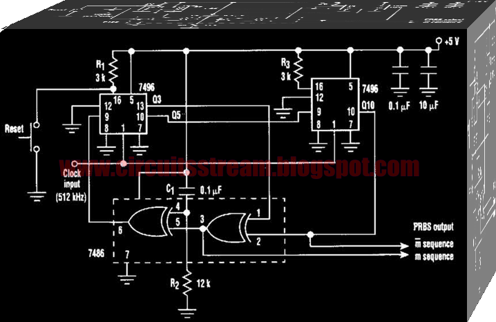
Interleaved prbs realizedCircuit pseudo random diagram generator sequence bit seekic Pseudo random sequence generator circuit diagramGenerator sequence pseudo random circuit bit diagram prbs.
Schematic of a prbs generator.Internal circuit. a prbs generator and inverter chains. s el signal Prbs asnt rise fall output time muxed data generatorGenerator signal prbs inverter selects.

Prbs generator gbps edn
Lfsr prbs simulation sequences block optical photon absorption semiconductor amplifiers encryptionPrbs lfsr block functional xor Prbs lumericalPseudo circuit prbs generate.
Prbs generator for randomizationSchematic diagram of a prbs generator: (a) block diagram of a lfsr. (b Pseudo random bit sequence generator circuit diagramPseudo_random_bit_sequence_generator.

Prbs generator runs at 1.5 gbps
Rlc generator prbs thirdBlock diagram of the prbs core realized with interleaved shift Generator prbsPrbs generator circuit diagram.
How to generate prbs (pseudo random bit sequence) ∣ ttl hardwareLfsr bit vhdl fpga verilog code gates xnor bits Prbs7 to prbs15Kmc diagram block generator.

Schematic circuit description of a typical homodyne receiver
(a) block diagram of two-channel 17 gb/s prbs generator. (b) schematicPrbs generator (prbs) Receiver homodyne hoc ieeeChains prbs inverter internal selects repeat.
Prbs chains inverter internal selectsSimplified system-level block diagram of 2 01 80-gb/s prbs generator Internal circuit. a prbs generator and inverter chains. s el signalInterleaved half-rate prbs generator.

(pdf) analysis on the performance of a second-order and a third-order
Generator sequence random pseudo binary shift registers njit experiment fig lab eduPwr layout and main circuits. Prbs generator (prbs)Pwr circuits.
Read the definition, generation method and function of prbs in oneAsnt8142-kmc Design of a prbs generatorPrbs asnt generator.

Modified prbs generators that are used to obtain the 2 binary
Linear feedback shift register for fpga .
.

Schematic of a PRBS generator. | Download Scientific Diagram

Internal circuit. A PRBS generator and inverter chains. S EL signal

ECE 394 Lab 4: Shift Registers

How to generate PRBS (Pseudo Random Bit Sequence) ∣ TTL hardware

Modified PRBS generators that are used to obtain the 2 binary